
A real world example - de-bouncing #
A practical use for this new functionality and the reason I started down this path in the first place is using assembly in interrupt service routines (ISRs). ISRs are code that is run in response to an interrupt, which is a processor generated signal that signifies something has happened. This could be an I/O pin changing state, a timer reaching a specific value, or a more sophisticated hardware peripheral signaling that something requires attention (e.g. a UART has received a byte). ISRs tend to be time-critical so reducing execution speed is an important consideration. We will also be able to use a feature of the e4thcom assembler to reduce size of the ISR code as well, which is helpful on a space constrained device like the MSP430.
The problem we are trying to solve here is that of switch debouncing. This excellent pair of articles by The Ganssle Group outlines the problem and some solutions in great detail and I recommend you take the time to read them. To summarise, when a physical switch is pressed or released, the switch contacts do not make a clean transition from open to closed or vice versa. Instead, the contacts will bounce, making and breaking contact several times before settling into the final state. This can cause problems for digital circuits that are expecting a single transition, as they may see multiple transitions instead (The ‘bouncing’ of the signal).
As the second article shows, there are a number of both hardware and software solutions to this problem. I have used a native forth version of the solution described in the article successfully in a number of projects, but I was always aware that the ISR could be improved with a more efficient implementation (both in cpu time and memory space).
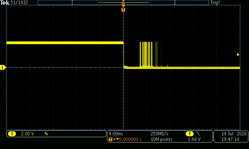
Below is a scope capture of a real switch that I am using in this circuit (Multiple switch activation cycles are shown here). The switch pulls the GPIO pin low when closed. As you can see, there are a number of bounces back to open when the switch is pressed, but they all seem to exist in the 0 - 10 ms range. We will use this window for possible bouncing in our implementation of the debouncer.
The software approach #
This is some forth code for the ISR (taking the approach from the Ganssle article), that is triggered by a timer interrupt. The hardware setup is left out for clarity, but the word switch? puts the state of the switch on TOS, and the variable press-count is incremented each time a valid press is detected.
$0 variable shift-state     \ 16-bit history; high 3 bits saturate to 1
0  variable press-count     \ debounced presses

: shift-isr ( -- )
  shift-state @ 2*                       \ shift window left
  switch? 1 and or                       \ append sample (1=released, 0=pressed)
  $E000 or shift-state !                 \ saturate top 3 bits, store
  shift-state @ $F000 = if               \ check for 12 consecutive pressed states
    1 press-count +!                     \ increment press-count
  then
;
The key thing to realise about this scheme is when the final unpressed state is detected (followed by 12 consecutive pressed states), the press is registered. The timing window of the ISR and the number consecutive pressed states required to register a press can be adjusted to suit the application, and more importantly, can be altered in software without changing the hardware. In the scope capture shown above, we will trap all bounces if we set the ISR to run every 2 ms and require 12 consecutive pressed states to register a press. This will give us a debounce window of 24 ms. This can be modified to suit different applications by changing the frequency that the ISR is invoked and the number of consecutive pressed states required to register a press.
Below is a visualisation of this working, each step showing a new invocation of the ISR, and the state of the shift register.
Now for the assembler #
This is the perfect opportunity to use our new assembler. Below is the assembler equivalent of the above forth code. The key difference is that the shift register state is kept in CPU register R08 rather than in memory, which saves cpu cycles and space in RAM. The switch? word is replaced with a single instruction to read the GPIO pin directly (and therefore ties it to the exact port and pin we are testing on this hardware).
code shift-isr
  R08 R08 add                      \ shift window left
  SW_BIT # P2IN & .b bit           \ flag Z=1 if line low (pressed)
  0<>? if, #1 R08 bis then,        \ append sample (1=released, 0=pressed)
  $E000 # R08 bis                  \ saturate top 3 bits, store
  $F000 # R08 cmp                  \ check for 12 consecutive pressed states
    =? if,
    #1 x[ press-count ] & add      \ increment press-count
  then,
end-code
Let’s step through the code line by line and see what the differences are between the forth and assembler versions.
R08 R08 add is the same as shift-state @ 2*, except we are using the free R08 register to hold the shift state, rather than a variable in memory. This skips a read and write to memory, saving cycles. We are implementing a left shift in both cases, but the forth version is using the 2* word (which uses the same add instruction under the hood).
The second and third lines of the ISR have a bit going on so let’s break it down. They are the equivalent of switch? 1 and or in the forth example but use a couple of features that are worth pointing out.
Firstly, you can import mcu specific definitions using \xas directive in the e4thcom session. You can both import MCU specific definitions that hold device specific addresses (such as hardware configuration addresses)
\xas MCU: MSP430FR2355
as well as declaring specific values you would like available to the assembler
\xas 1 equ SW_BIT \ P2.0 mask, switch connected to pin 0 of port 2
The key point being, neither of these values are available to the forth code on the device, or take up any space in the dictionary. They are simply converted to real values when the assembler runs from the e4thcom session.
What we are doing in this snippet
SW_BIT # P2IN & .b bit      \ Z=1 if line low (pressed)
0<>? if,  #1 R08 bis  then,
is checking the SW_BIT ($0001) of the P2IN register (The address of which is declared in the MCU specific file imported with the MCU: directive), and if it is low (the switch is pressed), we set the low bit of R08 (the equivalent code to switch? 1 and or from the forth implementation).
$E000 # R08 bis is exactly the same as $E000 or shift-state ! from the forth version, saturating the top 3 bits of the shift register (but using a register instead of a variable in memory). The e4thcom documentation has more detail on the \xas MCU specific definitions and how to use them in your code.
The final part of the asm code again does the same thing as the forth version, we check to see if we’ve reached the threshold of 12 consecutive pressed states by comparing the R08 temp register to the constant $F000 and if so, we increment the press-count variable.
$F000 # R08 cmp
=? if,
#1 x[ press-count ] & add \ press-count++
then,
Here we see the x[ press-count ] syntax which asks the target device for the address of a variable in the dictionary, which is then used with the add instruction to increment the value at that address ( & ) . In this way we can read and write forth variables from assembly code.
Benchmarks #
Well that’s lot of work to get to this point, but let’s see how the two implementations compare in terms of speed and size.
You can benchmark the size using the word here, which returns the current dictionary pointer, and the size of the code is simply the difference between the two here calls before and after the code is compiled.
Cycles are measured using a built-in timer on the device.
| forth | asm | |
|---|---|---|
| Total size | 440 bytes | 256 bytes |
| CPU cycles | 69 | 22 |
So the asm version is ~3× faster (69 → 22 cycles) and ~2× smaller (440 → 256 bytes).
There is a 40-byte overhead included here for code and end-code words as a one-time fixed cost. Additional asm words will use these definitions.
Visualising the ISR execution time #
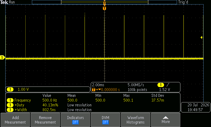
We can modify the ISR to toggle a GPIO pin when it is invoked, then clear it when it completes. Viewing on the scope, this shows us the amount of time the program is spending servicing the interrupt (Although as this pin setting occurs within the ISR code, it doesn’t account for the time taken to call and return to the ISR itself, which is a few cycles). The scope’s measurement feature confirms the ISR is being called every 2ms and takes around 800ns to execute, which at the 24MHz clock speed of the MSP430 is around 20 cpu cycles.
Conclusion #
Over the course of this series, we have seen how to use the e4thcom assembler to write assembly code for the MSP430 in a forth environment. We then used this in a real life application, where opting for assembly over forth saved space in the dictionary and cpu cycles in a time-critical ISR.
Using the assembler in this way we get the best of both worlds, the speed and efficiency of assembly code for hot paths, with the ease of use and flexibility of a forth environment for writing and debugging higher level application code.
Source files #
- db-ganssle.fs — the forth version of the debouncer
- db-ganssle-asm.fs — the assembler version of the debouncer