NOTE: This PCB is probably considered obsolete, see conclusion for links to more recent PCBs for the Modxo project. The rest of the information presented may still be useful when attempting a Modxo PCB build/install
Introduction #
The original Xbox was the first console I bought as an adult and the first I’d owned since having a Sega Master System as a child (I’d switched to being a PC gamer in my teens/university). From memory, it first launched in Australia with a pretty steep asking price of almost $AUD800, but started to be discounted not long after that. I think I paid around $400 for mine and with it I picked up Halo and the first Forza Motorsport.
The gaming was great and many a share house laugh was had playing multiplayer Halo on our tiny CRT TV. Not long after that however, the use of the Xbox as a media player and MAME machine came to my attention and I wanted in on the action. I sourced a mod-chip online (Team Xodus’s Matrix modchip) and flashed a custom BIOS that allowed me to use these new features. As time went by, the Xbox became more of a media player and then eventually when the demands of modern codecs became too much for the hardware, it was replaced by a media PC (still running a newer version of XBMC).
2020 and its attendant surplus of ‘sitting around time’ rekindled my interest in retro gaming and in addition to buying other older consoles, I started to play with my original Xbox again. The problem I faced was the booting the Xbox was becoming more and more unreliable. The mod-chip I had installed used pogo pins to connect to the LPC header pads, and I was finding I needed to realign them more and more often (Maybe this was caused by corrosion/buildup on the pogo pins / contact points?). This was an annoying procedure that involved basically taking the Xbox apart, so when I saw a Macho Nacho video about a new opensource mod-chip project called Modxo, I decided I would try to build one in an attempt to cure my booting issues once and for all.
Board & BOM #
The Gerber files for the board (as a zip file) are available on the Modzvilleusa Github and are ready to upload to pcb manufacturer as is. I chose JLCPCB for this project as I’ve used them before for other projects and have always been happy with the results.

Uploading the file is as simple as dragging the zip file onto the ‘Add Gerber File’ box on the JLCPCB website. The website will then show a preview and allow you to select a number of different options. The defaults were fine for this project (it’s a 2 layer board), but I did change the colour to blue as it matches the colour of the RP2040-Zero.
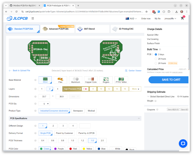
Due to a site discount the 5 boards cost me $2.00 USD + Shipping, so depending on where you live, you’re probably looking at around $10 / 5 boards.
For components, I switched out the RP2040-Tiny for an RP2040-Zero because it doesn’t require the usb header board and was also more available (it does however have the same pinout). I also picked green for the LED. Opting for the RP2040-Zero meant that I also needed additional headers to mount the RP2040-Zero to the board (as the board has components on both sides).
| Designator | Value | Footprint | Unit Cost (USD) | Qty | LCSC Component |
|---|---|---|---|---|---|
| R1, R2, R3, R4, R5 | 100 | 0603 | $0.001 | 5 | C105588 |
| R5 | 1k | 0603 | $0.001 | 5 | C105588 |
| D6 | SD0805S020S1R0 | 0805 | $0.265 | 1 | C143773 |
| Header (mod) | 7 pin female | P=2.54 | $0.0811 | 1 | C38844 |
| Header (Xbox) | 7 pin male | P=2.54 | $0.0559 | 1 | C492424 |
| +/- | LED | 0603 | $0.0172 | 1 | C215098 |
| RP2040 Zero | $5.0034 | 1 | C5350143 | ||
| Header (RP2040 Zero) | 1x9 pin male | P=2.54 | $0.0326 | 2 | C492408 |
| Header (RP2040 Zero) | 1x5 pin male | P=2.54 | $0.0278 | 1 | C492404 |
Total component cost per board is less than $6.00 USD, leading to a total cost of around $8.00 USD per board (minimum quantities and shipping costs play a bit of a part here, but I had most of the passive components in stock already).
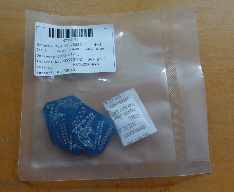
Board fabrication and shipping as well as component shipping took around 2 weeks to Australia (if you selected the cheapest shipping option).
Build & Check #
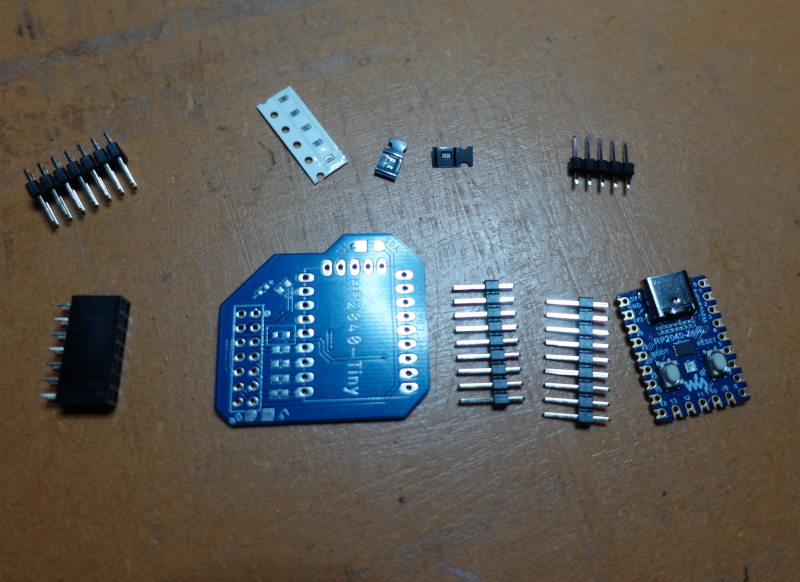
For assembly order, I started with the surface mount components (R1..R5, D1 and LED), then the RPZero headers, then the RPZero itself, then finally the female LPC header. The blocking diode D6 orientation is a bit hard to determine from the repo, but its purpose is to prevent the 5v from the RPZero entering back via the LPC header, so the cathode should be connected to the RPZero 5v pin (the side with the faint line on it). I have included a check for this in the testing section below.

It doesn’t really matter which way around the pin headers are mounted (long or short side up) as you’ll probably want to trim them once the RPZero is mounted. Plenty of flux when soldering the RPZero to the headers will ensure a good connection.
PCB with headers attached before soldering the RPZero
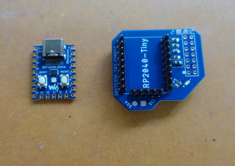
The completed board should look something like this
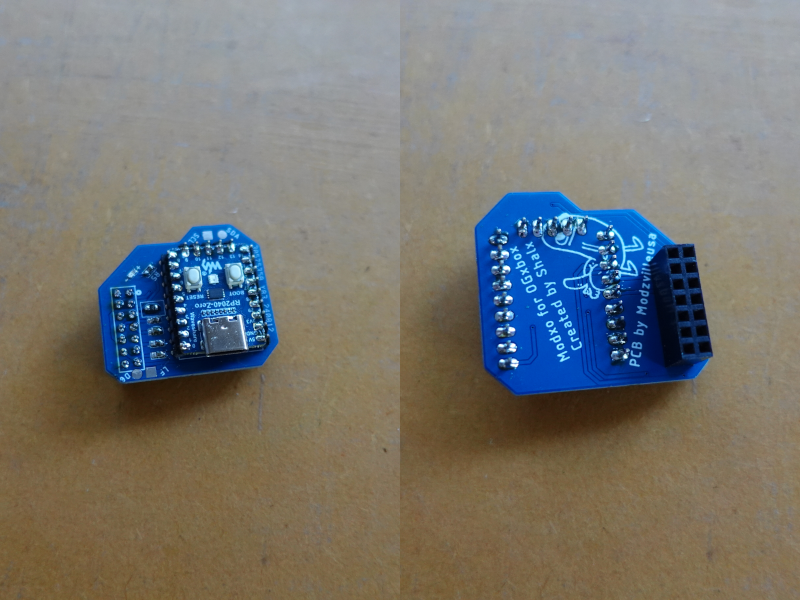
Now would be a good time to clean the board with some isopropyl alcohol and a toothbrush to remove any flux residue, then check the board with a multimeter.
Using the pinout diagram supplied by the project
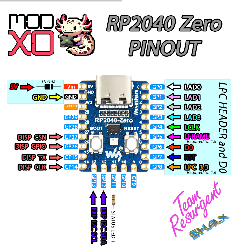
and remembering pin 1 of the LPC header is the bottom right (looking down on the mod-chip from the ’top’), we can do the following checks with a multimeter
| Test | Positive Lead | Negative Lead | Expected | Purpose |
|---|---|---|---|---|
| Diode | LPC Pin 6 | RPZero Vin | Small positive voltage | Blocking diode correct orientation |
| Diode | LED + | LED - | Diode Lights | LED correct orientation |
| Continuity | LPC Pin 2 | LPC Pin 12 | Continuity (Beep) | Ground connection OK |
| Continuity | LPC Pin 2 | RPZero GND | Continuity (Beep) | Ground connection OK |
| Continuity | RPZero Vin | RPZero GND | No Continuity | No short between Vin and GND |
| Continuity | RPZero GP6 | D0 Pad | Continuity (Beep) | D0 connection |
| Resistance | RPZero GP0 | LPC 11 Pin | ~100 Ohms | LAD 0 connection |
| Resistance | RPZero GP1 | LPC 10 Pin | ~100 Ohms | LAD 1 connection |
| Resistance | RPZero GP2 | LPC 8 Pin | ~100 Ohms | LAD 2 connection |
| Resistance | RPZero GP3 | LPC 7 Pin | ~100 Ohms | LAD 3 connection |
Current setup #
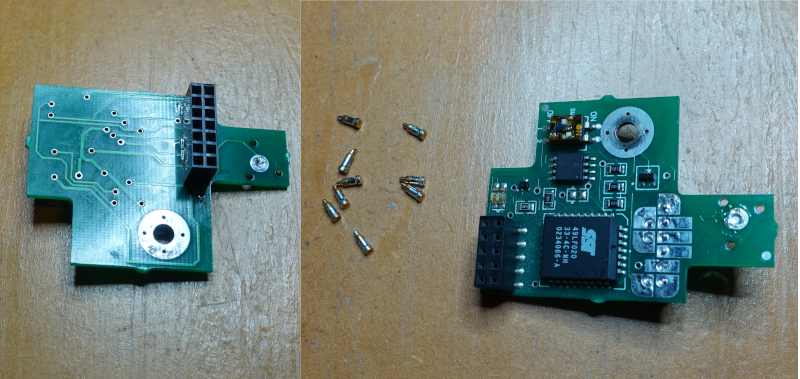
I was slightly concerned that getting the new mod-chip working in my Xbox might be a bit of a challenge, so I decide to rule out any possible existing issues with my current setup. As mentioned earlier, my exiting mod-chip had been working fine but had begun needing constant realignment of the pogo pins to boot without error. After doing a bit of searching and digging up the manual (for dip switch config details) I spent a frustrating half hour or so trying to get the Xbox to boot. It wasn’t until then that I realised the solution to my problem was already available. The pogo pins on the old mod-chip connect to the same LPC pads on the motherboard as the new mod-chip, so if I just removed the pogo pins and replaced them with a header, I could solder the corresponding male header to the motherboard and test. This required soldering some wire the D0 point on the motherboard, but this would also be required for the new mod-chip.
The header pcb footprint needs to have the solder removed (at least on my v1.0 motherboard)
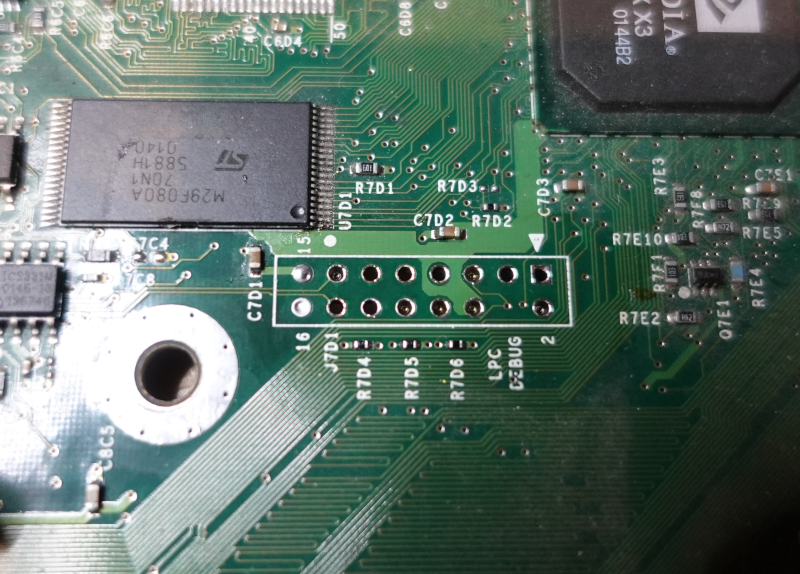
Note that pin 4 of the LPC header does not have a hole/pad for the header, so this needs to be removed from the header before mounting (a slight yank with a pair of pliers will suffice).

Soldering in the header and using a shortish length of enamel wire to connect the D0 point to the header meant I was ready to reconnect the old mod-chip and test. (The D0 point for my v1.0 motherboard is shown, you might need to check what location it is on later revisions).
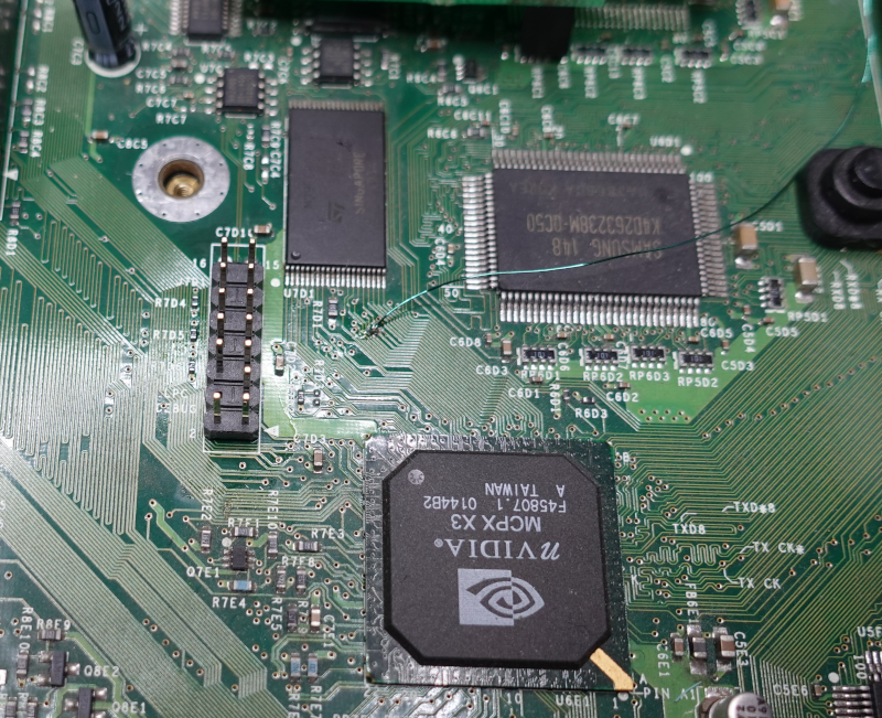
The original mod-chip with the pogo pins removed and the header installed
Once the D0 wire was soldered onto the mod-chip and the DIP switches were set back to the correct configuration to boot, the xBox started successfully (and reliably, actually solving the problem I was building the Modxo to solve)
Config & Install #
The Configuration Instructions on the Team Resurgent Github are pretty straightforward. Essentially you have to
- Load the lastest release of the Modxo firmware onto the RPZero.
- Package the BIOS file you want to use using their online tool.
- Load this packaged BIOS file (UF2) onto the RPZero.
The Raspberry Pi Pico has a great feature where you can load any firmware onto it by booting into a firmware mode (by holding down the BOOTSEL button while plugging it in via USB) then dragging and dropping the firmware file onto the mounted drive. This is far more convenient than having to use a programmer to load the firmware.
The modxo bios packer web tool

As I think most BIOS replacement files use some Microsoft proprietary code, I’m not going to link any here, but the BIOS file I opted for was the latest (at the time) version of the Cerbios BIOS. Development seems to still be happening and I didn’t have too much trouble finding a BIOS file to use.
Once the BIOS was loaded onto the RPZero, it was simply a case of replacing the old mod-chip, resoldering the D0 wire and putting the whole thing back together. I used a bit of Kapton tap to hold the enamel wire in place and to prevent possible stress on the motherboard solder joint.
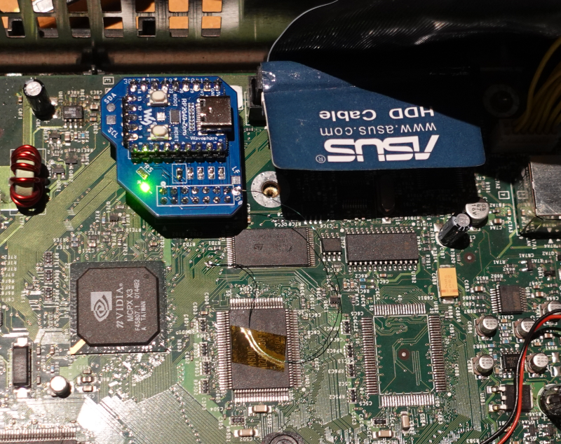
Time for a test toast

Success!
Conclusion #
Even though soldering actual pin headers to the motherboard on my existing mod-chip actually solved my original reliability problem, I’m still glad I built the Modxo board and will investigate some of the features the new bios will enable in the future. Not having to dig out an old parallel port programmer (and a machine able to use one) to update the bios is a big plus.
Whilst completing the build I rechecked the ModsVilleUSA Github (to confirm the D6 orientation) and noticed that there have been newer releases of PCB boards for the project, which I probably would have built instead if they had existed at the time. The repo mentions ‘stability fixes’ but I’m not sure if that refers to the Modxo firmware or the PCB itself.
Whilst doing this write-up, I realised I’d used a 100 ohm resistor to current limit the LED, but I will be updating this to a higher value next time I’ve got the iron on.
On other thing I will probably do at some stage is put a dab of superglue in the pin 4 hole of the LPC header on the mod-chip to prevent the accidental misalignment of the header when connecting the mod-chip to the motherboard.
All in all I’m happy with how it turned out and convinced this an achievable weekend project for someone with a bit of soldering experience.